DGC'S FURNACE INSPECTION SERVICES OFFERS INFRARED THERMOGRAPHY
- DGC AFRICA
- May 25, 2022
- 2 min read
Updated: Apr 9, 2024
DGC offers a comprehensive range of Furnace Inspection Services to the metals smelting, mineral processing, thermal energy, and industrial furnace industries.
The services are offered in alliance with ADI Industrial Services; a Belgium-based Service Company that has been performing furnace inspections in different industries for more than 25 years.
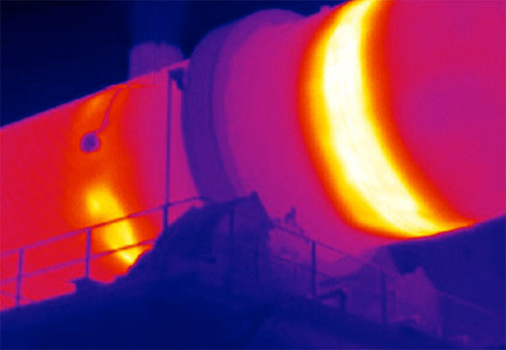
The Furnace Inspection Services allow for real-time furnace diagnostics and assisting operators in assessing the state of furnaces at their working temperatures. The services are mainly based on two techniques; infrared thermography for external inspection and high-temperature endoscopy for internal inspection, this article will focus on infrared thermography.

Infrared thermography is aimed at providing accurate images representing the thermal status of a furnace’s shell, its value is derived from the accurate interpretation of the output images in their industrial context. The processed information is integrated into users’ preventive maintenance programs.
The technique enables operators to constantly monitor a furnace’s metallic shell status, identify or localize damaged areas (internal/external) as well as estimate the remaining refractory lining thickness.
Regular monitoring helps operators in maintaining production within the optimum operating conditions, at optimum costs, with optimized yields, and minimal industrial risks in terms of safety.
BENEFITS
The benefits of Infrared Thermography are summarised below:
Compilation of comprehensive records of refractory lining wear.
Reduced unplanned stoppages.
Improved furnace equipment availability.
Efficient planning for scheduled shutdowns and refractory materials supplies.
Knowledge sharing with plant maintenance staff.
Mitigation of major damages to the furnace.
Enhanced energy efficiency of operations.
APPLICATION EXAMPLE: PROCESS VESSELS
To correctly interpret the images, they are analyzed in consultation with equipment drawings.
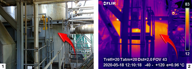
In images 1 to 4:
We see a warmer surface around the entire circumference of the vessel at the platform’s height (about 5m above the ground). In images 2 and 4 we see lighter spots, indicating hot spots.


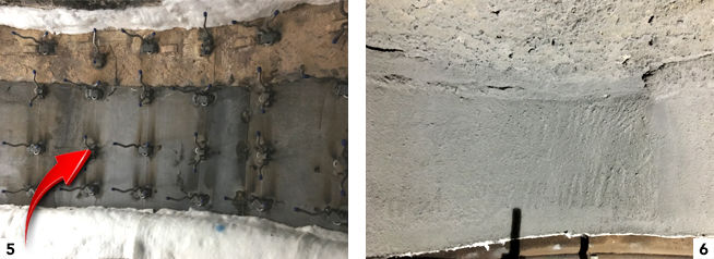
Image 5 :
indicates the positions of anchors on the shell before the refractory lining was installed.

In image 8:
We notice that the hot spots appear to be in the pattern of the anchors, indicating the extent of refractory lining wear.
ABOUT OUR COMPANY, HISTORY, AND PARTNERS
Dickinson Group of Companies (DGC) was founded in 1910. For comprehensive information about our company's History, Vision & Values, Strategy, Global Alliances, Africa Footprint, Commitment to Safety, Anti-Corruption Policy, References, and Industrial Solutions, please visit our website.


Comments